Understanding Machining Tolerances in Fabricated Parts
May 10, 2025 1:21 pm Leave your thoughtsMachining tolerances are a critical aspect of the manufacturing process, ensuring that parts meet specific standards and function as intended in their final application. Whether it’s in aerospace, automotive, medical, or any other industry that relies on precision, machining tolerances play a pivotal role in ensuring the quality and performance of the final product. Understanding how these tolerances work, the different types, and how they affect fabrication is essential for both manufacturers and engineers. In this blog, we will dive into the concept of machining tolerances, their significance in fabricated parts, and how they can be applied effectively in the production process.
The Importance of Machining Tolerances in Fabricated Parts
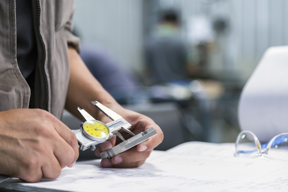
Machining tolerances define the allowable variation in the dimensions and geometries of a part that can be produced through machining processes such as turning, milling, drilling, or grinding. These tolerances are crucial because they determine how closely the final part will resemble the design specifications. Without proper machining tolerances, a part may not fit into an assembly, function incorrectly, or even cause system failures in high-precision applications.
For instance, in the aerospace industry, a small deviation from the specified tolerance could result in a catastrophic failure of an aircraft component. Similarly, in the medical field, a part that does not meet tight tolerances could lead to the malfunction of medical devices, potentially risking patient safety. Therefore, machining tolerances are directly tied to the functionality, reliability, and safety of the final product.
One of the main reasons machining tolerances are so important is that it allows manufacturers to produce parts that are both cost-effective and high-quality. By specifying tolerances that balance precision and production efficiency, manufacturers can avoid the unnecessary cost of producing parts with excessive precision when it’s not required. It also ensures that parts can be made consistently, meeting the demands of customers and regulatory standards.
Types of Machining Tolerances
There are several types of machining tolerances, each suited to different manufacturing needs. These types of tolerances help engineers and manufacturers specify the acceptable limits of variation for different features of a part. The following are the most common types of machining tolerances used in fabricated parts.
Dimensional Tolerances
Dimensional tolerances are the most basic form of machining tolerance. They define the permissible variation in the size of a part, such as its length, width, height, or diameter. These tolerances ensure that the part’s dimensions are within an acceptable range, allowing it to fit with other components in an assembly.
For example, if a cylindrical part is specified to be 50 mm in diameter, the dimensional tolerance might allow it to be between 49.95 mm and 50.05 mm. This variation ensures that the part can still be assembled without any issues, even if there are slight inconsistencies during production. Dimensional tolerances are typically specified as a range (e.g., ±0.05 mm) or as a specific value for the upper and lower limits of acceptable variation.
Geometric Tolerances
Geometric tolerances go beyond just size and are concerned with the shape, orientation, and position of a part. These types of tolerances are essential when a part needs to maintain a specific geometric relationship with other parts or when it needs to perform specific functions, such as fitting into a hole or engaging with another component.
Geometric tolerances can include parameters such as flatness, straightness, roundness, cylindricity, parallelism, perpendicularity, angularity, and position. For example, a part might be required to have a flat surface within a specified range of variation, ensuring that it mates properly with another surface. Similarly, angularity tolerance might be used to ensure that two features of a part are at the correct angle to each other, within a defined range.
Surface Finish Tolerances
Surface finish tolerances specify the required texture of a part’s surface, which can affect the performance and aesthetics of the final product. A part’s surface finish is determined by the roughness, waviness, and lay of the material. These characteristics are important in applications where the part interacts with other surfaces or components, such as in sealing applications, or when aesthetic appearance is critical.
Surface finish is typically measured in terms of roughness average (Ra), which quantifies the average height of surface peaks and valleys. The more precise the surface finish, the smoother the surface will be, and the lower the Ra value. For instance, a smooth surface might have an Ra value of 0.1 micrometers, while a rougher surface may have an Ra of 5 micrometers. Understanding the required surface finish tolerance ensures that parts will perform optimally in their intended environment.
Positional Tolerances
Positional tolerances specify how accurately a feature must be located in relation to another feature. This is particularly important for parts that need to be assembled with other components, where precise location and alignment are critical for proper function. Positional tolerances control the allowable deviation from the true position of a feature, such as a hole or slot, in relation to a reference point or feature.
For example, a hole might be specified to be located within 0.1 mm of a certain position relative to other features on the part. If the hole is drilled outside this tolerance, the part may not align properly with the corresponding holes in an assembly. Positional tolerances can significantly impact the ease of assembly and the functionality of the final product.
How Machining Tolerances Are Specified
Machining tolerances are typically specified using a system of symbols and notations outlined in international standards such as the ISO 1101 or ASME Y14.5. These standards provide a clear and consistent way to define tolerances, making it easier for engineers, manufacturers, and inspectors to communicate the required specifications for a part.
For dimensional tolerances, the range of acceptable values is usually specified directly next to the dimension. For example, a dimension might read “50 ±0.05 mm,” indicating that the part’s size can vary from 49.95 mm to 50.05 mm. For geometric tolerances, a set of symbols is used to represent different features, such as flatness (⎯⎯⎯), roundness (⌀), or perpendicularity (⊥).
In the case of positional tolerances, a feature control frame is often used, which includes information about the type of tolerance, the reference point or feature, and the allowable deviation. This system ensures that all parties involved in the manufacturing process are on the same page and helps prevent errors that can arise from unclear or inconsistent specifications.
The Challenges and Impact of Machining Tolerances
While machining tolerances are essential for ensuring the functionality and reliability of fabricated parts, they also present several challenges. The tighter the tolerance, the more difficult and costly it is to achieve. For example, producing parts with tight tolerances often requires specialized machinery, tools, and techniques, all of which can increase production time and costs. Additionally, the risk of defects or part rejection increases as tolerances become more stringent, which can lead to waste and inefficiencies in the manufacturing process.
Moreover, machining tolerances can impact the design and material choices for a part. For instance, parts made from harder materials may be more challenging to machine to tight tolerances due to the difficulty in cutting or shaping the material. Similarly, designers must balance the need for precision with the cost and time constraints of the manufacturing process. Specifying tolerances that are too tight for the requirements of the part can lead to unnecessary production costs, while overly loose tolerances might result in parts that don’t function correctly or fail prematurely.
In some cases, manufacturers may need to engage in advanced machining techniques, such as precision grinding or electrical discharge machining (EDM), to achieve the required tolerances. These methods can be slower and more expensive than traditional machining processes, but they are necessary for applications where extreme precision is required.
Conclusion
Machining tolerances are a vital aspect of producing high-quality fabricated parts. Whether it’s dimensional, geometric, surface finish, or positional tolerances, each type plays a crucial role in ensuring that a part fits, functions, and performs as intended. While machining tolerances can introduce challenges in terms of cost and complexity, they are necessary for ensuring the safety, reliability, and efficiency of parts across a wide range of industries. By understanding the different types of machining tolerances and how to apply them effectively, manufacturers can produce parts that meet the required specifications while maintaining a balance between cost and quality.
Need Steel Fabricators in Hermiston, OR?
NW Metal Fabricators, Inc. is a family-owned business that has been servicing customers in Hermiston, Oregon since 1986. We have more than 100 years of experience in the food-processing industry and specialize in the custom production of storage bins, conveyors, catwalks, handrails, gates, storage tanks, water heater tanks, sanitary piping, steam piping, and trailer truck hitches. NW Metal Fabricators, Inc. is an accredited member of the local Chamber of Commerce. We are a dedicated business where quality always comes first. Our customers know that they can count on us to make sure that their products are hand-crafted to meet their specifications. Contact us today to learn more about what we can do for you!
Categorised in: Metal Fabrication
This post was written by admin